 |
IPSDK 4.2
IPSDK : Image Processing Software Development Kit
|
|
IPSDK 4.2
IPSDK : Image Processing Software Development Kit
|
IPSDK is a rich and fast image processing library. However, Python developpers may want to take the most of Numpy powerful functionalities. To do so, IPSDK uses a Python image class with a numpy array as attribute of the class. This means that the numpy array and the IPSDK image class share the same buffer and modifying one will also modify the other. This specificity has two advantages :
First, we import the packages PyIPSDK and numpy :
We can then create or load an image and access to its corresponding numpy array :
Reciprocally, it is possible to initialize a numpy array into an IPSDK image. The wrapper fromArray and its derivatives are used to initialize an IPSDK image assigning the input numpy array to the array attribute in the PyIPSDK image class.
Here is an example of initializing an IPSDK image from a numpy array :
Yet, the data are not copied and both structures correspond to the same memory location, which implies that modifying the array will modify the input image and vice versa. Running the following commands allow to verify this :
We can also interpret the array as specific IPSDK image buffer type. The array have to respect some constraints :
fromRgbArray, 3d arrays can be interpreted as an RGB image : the first dimension size must equal 3fromBinaryArray, arrays can be interpreted as a binary image : the image must be a 2d or 3d array and the data type must be boolean, signed or unsigned 8-bits integer,fromLabelArray, arrays can be interpreted as a label image : the image must be a 2d or 3d array and the data type must be unsigned 16 or 32-bits integer.For other image formats, it is also possible to specify a geometry to fromArray and inform IPSDK how to interpret the data. For instance, a way to initialize a 3d RGB PyIPSDK image from a 4d array can be done with the following instructions :
We define some variables for the image dimensions along the x, y and z-axis to highlight that the order of the values differs between the numpy array and the IPSDK image definitions. Indeed, numpy arrays define first the size along the z-axis, then along the y-axis and finally along the x-axis whereas IPDK geometry wrappers specify sizeX first, then sizeY and finally sizeZ.
When a IPSDK Python image is created, the associated numpy array is C-Contiguous. This means that two successive elements have the indices x and x+1, the first pixel in the line y follows the last one in the line y-1, etc.
However, this property may not be respected, for instance, when the numpy array contains alignment data for display purpose. This case is illustrated by the following image.
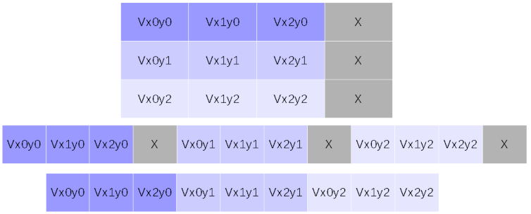
The image contains pixels noted  , with
 ![$ i, j \in [0, 2] $](form_294.png) and alignment data are represented by 'x' values (see the illustration on the top). The image buffer is represented in memory as raw data, where 'x' values appear between Vx2y0 and Vx0y1, between Vx2y1 and Vx0y2 and after Vx2y2 (see the illustration on the middle). This is not acceptable to efficiently process data within the IPSDK famework, which needs C-contiguity (see the illustration on the bottom).
and alignment data are represented by 'x' values (see the illustration on the top). The image buffer is represented in memory as raw data, where 'x' values appear between Vx2y0 and Vx0y1, between Vx2y1 and Vx0y2 and after Vx2y2 (see the illustration on the middle). This is not acceptable to efficiently process data within the IPSDK famework, which needs C-contiguity (see the illustration on the bottom).
One way to avoid this, it is possible to copy the array without alignment data into a new numpy array. However, it can uselessly require too much space in memorythe for large images. To handle this issue, IPSDK can detect non contiguity and creates a copy of needed plans instead of directly using the numpy array buffer if the contiguity is not respected. This way, a copy is indeed allocated, but only for a subpart of the image.
This behaviour is masked to the user, who only needs to call the PyIPSDK.fromArray() function. Moreover, IPSDK provides the functions PyIPSDK.fromDigisens() and PyIPSDK.toDigisens() to interface data with DigiXCT. These two functions allows to manage the compatibility between IPSDK and DigiXCT images, where the contiguity issue described above can happen.
It is important to note that this is only possible when alignment data are present at the end of lines and columns. If they are placed between data in the same line, IPSDK can not manage the numpy array and it is necessary to copy the entire image without the alignment data. This is illustrated by the figure below.
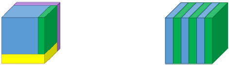
The left sub-image shows an acceptable case where the image data appears in blue and alignment data are green along the x-axis, yellow along the y-axis and purple along the z-axis. The right sub-image illustrates the unhandled case where alignment data are alternated with usefull data.
