 |
IPSDK 4.2
IPSDK : Image Processing Software Development Kit
|
|
IPSDK 4.2
IPSDK : Image Processing Software Development Kit
|
A morphological structuring element (SE) is a binary shape used by morphological operators (such as erosion, dilation, ...) to specialize operator behavior.
In 2d case, a morphological structuring element (associated to class ipsdk::StructuringElementXYInfo) is represented by a collection of offsets (associated to class ipsdk::OffsetXY) defining its shape.
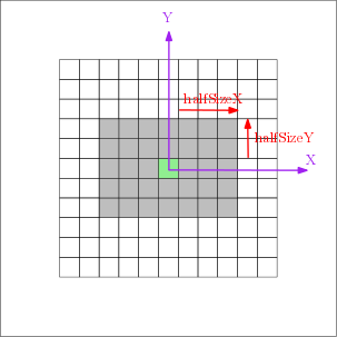
Rectangular structuring elements are defined by their half size along X and Y axis (  and
and  ) and aggregate all offsets such as :
![\[ SE[halfSizeX, halfSizeY] = \left \{ (o_x, o_y) / \left | o_x \right | \leqslant halfSizeX \& \left | o_y \right | \leqslant halfSizeY \right \} \]](IPSDKCore_form_140.png)
Full size of structuring element is then defined by :
![\[ \left \{ \begin{matrix} sizeX = 2 \times halfSizeX + 1 \\ sizeY = 2 \times halfSizeY + 1 \end{matrix} \right . \]](IPSDKCore_form_141.png)
The following C++ example illustrates the definition of a rectangular morphological structuring element :
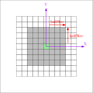
The following C++ example illustrates the definition of a square morphological structuring element :
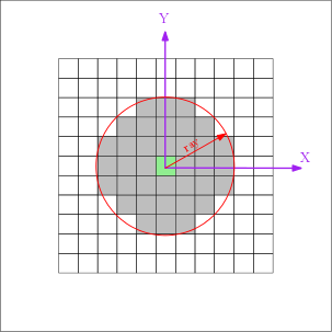
Circular structuring elements are defined by their radius and aggregate all offsets enclosed in associated circle :
![\[ SE[radius] = \left \{ (o_x, o_y) / o_x^2 + o_y^2 <= radius^2 \right \} \]](IPSDKCore_form_142.png)
The following C++ example illustrates the definition of a circular morphological structuring element :
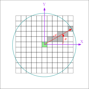
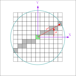
Half linear structuring elements are defined by an orientation and a radius and aggregate offsets at the intersection of associated direction and circle :
![\[ SE[\theta, radius] = \left \{ (o_x, o_y) / \exists \lambda \in \mathbb{N}^+ / o_x=\lambda \cos{\theta}, o_y=\lambda \sin{\theta} \& o_x^2 + o_y^2 <= radius^2 \right \} \]](IPSDKCore_form_143.png)
The following C++ example illustrates the definition of a half linear morphological structuring element :
Linear structuring elements are defined by an orientation and a radius and aggregate offsets at the intersection of associated direction and circle :
![\[ SE[\theta, radius] = \left \{ (o_x, o_y) / \exists \lambda \in \mathbb{N} / o_x=\lambda \cos{\theta}, o_y=\lambda \sin{\theta} \& o_x^2 + o_y^2 <= radius^2 \right \} \]](IPSDKCore_form_144.png)
The following C++ example illustrates the definition of a linear morphological structuring element :
In 3d case, a morphological structuring element (associated to class ipsdk::StructuringElementXYZInfo) is represented by a collection of offsets (associated to class ipsdk::OffsetXYZ) defining its shape.
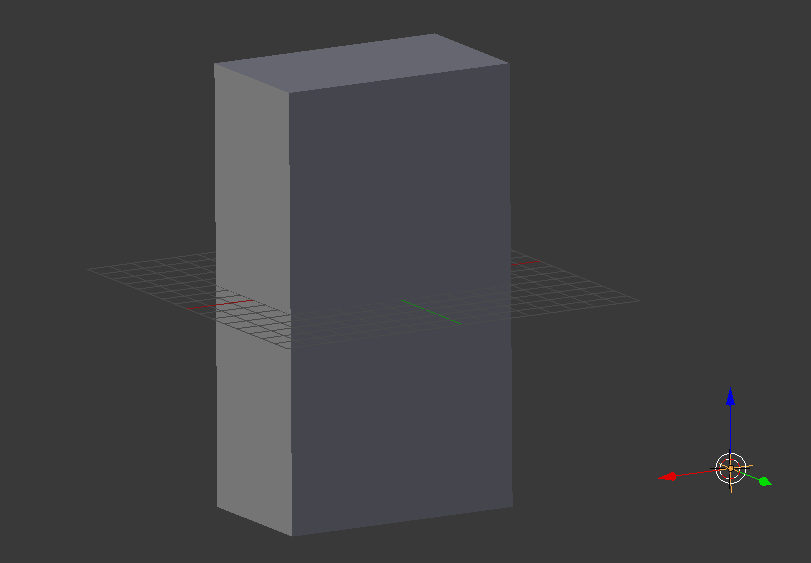
Rectangular structuring elements are defined by their half size along X, Y and Z axis ( , and  ) and aggregate all offsets such as :
![\[ SE[halfSizeX, halfSizeY, halfSizeZ] = \left \{ (o_x, o_y, o_z) / \left | o_x \right | \leqslant halfSizeX \& \left | o_y \right | \leqslant halfSizeY \& \left | o_z \right | \leqslant halfSizeZ \right \} \]](IPSDKCore_form_146.png)
Full size of structuring element is then defined by :
![\[ \left \{ \begin{matrix} sizeX = 2 \times halfSizeX + 1 \\ sizeY = 2 \times halfSizeY + 1 \\ sizeZ = 2 \times halfSizeZ + 1 \end{matrix} \right . \]](IPSDKCore_form_147.png)
The following C++ example illustrates the definition of a rectangular morphological structuring element :
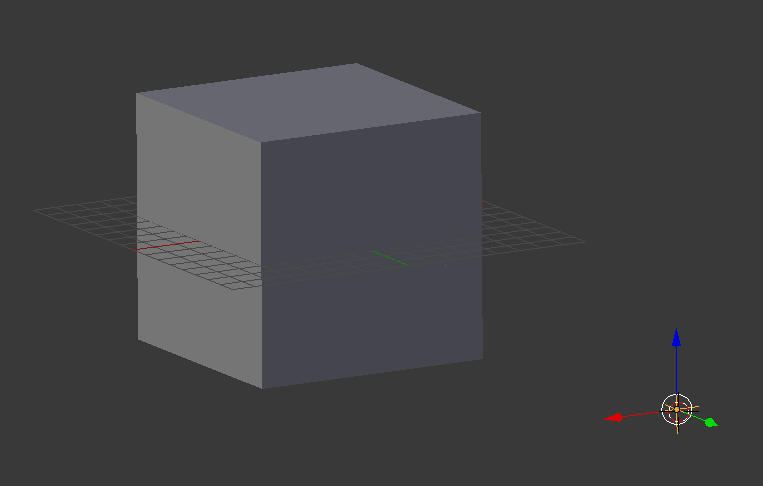
The following C++ example illustrates the definition of a cubic morphological structuring element :
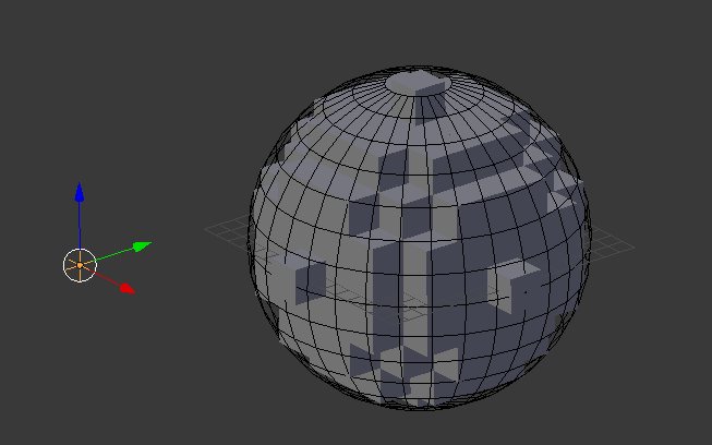
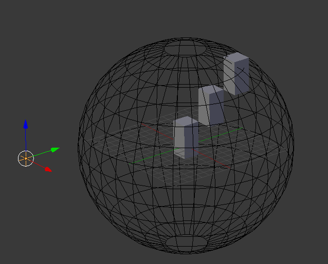
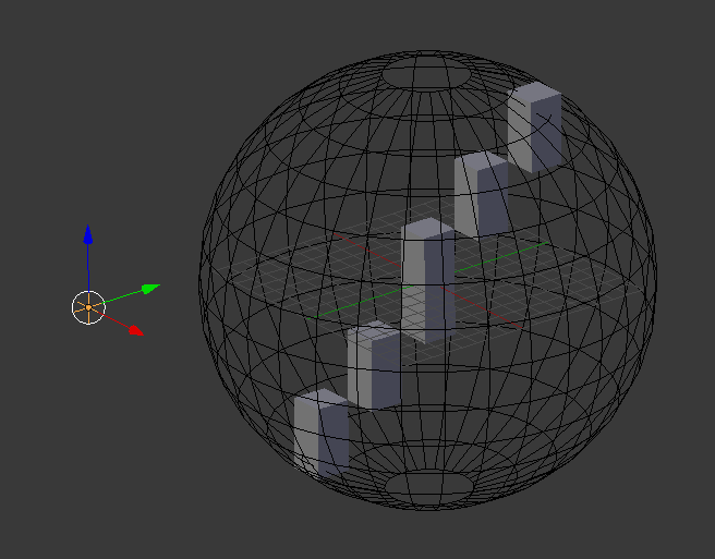
Spherical structuring elements are defined by their radius and aggregate all offsets enclosed in associated sphere :
![\[ SE[radius] = \left \{ (o_x, o_y, o_z) / o_x^2 + o_y^2 + o_z^2 <= radius^2 \right \} \]](IPSDKCore_form_148.png)
The following C++ example illustrates the definition of a spherical morphological structuring element :
Half linear structuring elements are defined by an orientation and a radius and aggregate offsets at the intersection of associated direction and sphere :
![\[ SE[\theta, \phi, radius] = \left \{ (o_x, o_y) / \exists \lambda \in \mathbb{N}^+ / o_x=\lambda \sin{\theta} \cos{\phi}, o_y=\lambda \sin{\theta} \sin{\phi}, o_z=\lambda \cos{\theta} \& o_x^2 + o_y^2 + o_z^2 <= radius^2 \right \} \]](IPSDKCore_form_149.png)
The following C++ example illustrates the definition of a half linear morphological structuring element :
Linear structuring elements are defined by an orientation and a radius and aggregate offsets at the intersection of associated direction and sphere :
![\[ SE[\theta, \phi, radius] = \left \{ (o_x, o_y) / \exists \lambda \in \mathbb{N} / o_x=\lambda \sin{\theta} \cos{\phi}, o_y=\lambda \sin{\theta} \sin{\phi}, o_z=\lambda \cos{\theta} \& o_x^2 + o_y^2 + o_z^2 <= radius^2 \right \} \]](IPSDKCore_form_150.png)
The following C++ example illustrates the definition of a linear morphological structuring element :
Erosion and dilation are the two fundamental morphological operations.
These operations use a flat (with values in [0, 1]) structuring element combined to a Minkowski sum (in case of dilation) or subtraction (in case of erosion). Formula associated to each of these operations are given by :
![\[ A \oplus B = \left \{ x / B_x \cap A \neq \varnothing \right \} \]](IPSDKCore_form_151.png)
![\[ A \ominus B = \left \{ x / B_x \subseteq A \right \} \]](IPSDKCore_form_152.png)
![\[ A \odot B = (A \oplus B) \ominus B \]](IPSDKCore_form_153.png)
![\[ A \circledcirc B = (A \ominus B) \oplus B \]](IPSDKCore_form_154.png)
![\[ G(A)_B = A \oplus B - A \ominus B \]](IPSDKCore_form_155.png)
![\[ T^D(A)_B = A \odot B - A \]](IPSDKCore_form_156.png)
![\[ T^L(A)_B = A - A \circledcirc B \]](IPSDKCore_form_157.png)
Structuring elements specific typology (shape) are detailed into :
These different typologies include rectangle, circle, sphere, lines, ...
Each of this shape can be used to respond to a specific need. We will try to illustrate this concept in the following section.
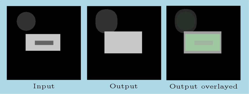
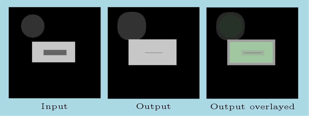
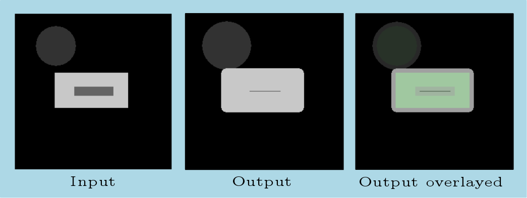
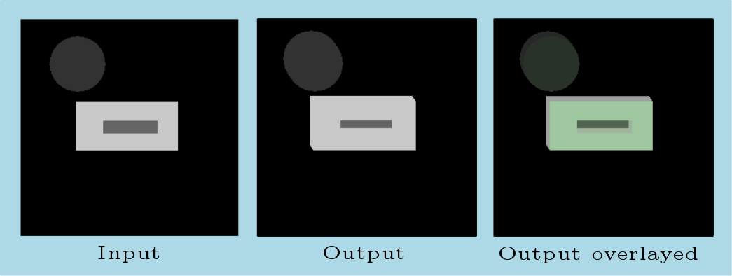
The following examples illustrates usage of different structuring element types for dilation 2d algorithm. A dilation 2d operation has been chosen for this use case but all these considerations could be extended to 3d case as well as other morphological operators.
 and
and  :
: 
 and
and  :
:  and :
and : 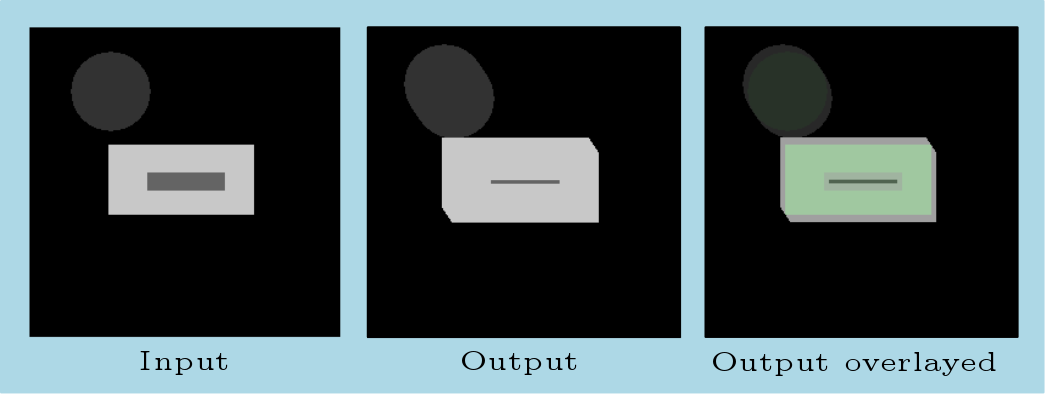
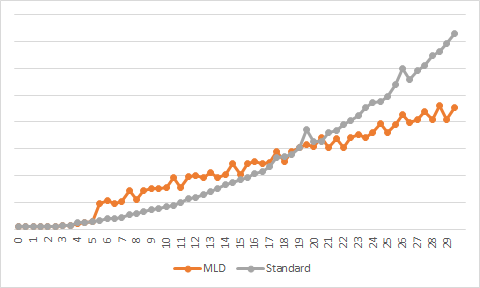
Circular 2d and spherical 3d structuring elements morphological operations can be optimised using a multi-level decomposition algorithm described in :
Multi-level decomposition of Euclidean spheres, Michael S. Vaz, Atilla P. Kiraly and Russell M. Mersereau, Proceedings of the 8 th International Symposium on Mathematical Morphology, Rio de Janeiro, Brazil, Oct. 10–13, 2007, MCT/INPE, v. 1, p. 461–472
This method allows to decompose convex and symmetric (with respect to x, y and z axis) structuring elements into a combination of elementary structuring elements.
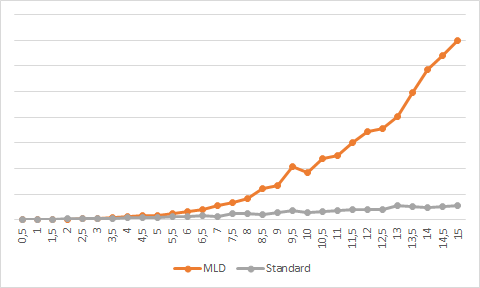
The following graph shows processing time comportment of a standard implementation of a morphological operation using a circular 2d structuring element versus its multi-level decomposition form :
The following graph shows processing time comportment of a standard implementation of a morphological operation using a spherical 3d structuring element versus its multi-level decomposition form :
Morphological 2d and 3d operations are optimized to swap between a standard and a multi-level decomposition implementation in function of these graphs.
